AMS1117 vs LM1117 vs LD1117: 3.3V LDO Regulator Comparison Guide
Comprehensive technical comparison of AMS1117, LM1117, and LD1117 LDO regulators for 3.3V applications. Includes specs, thermal performance, and selection criteria.
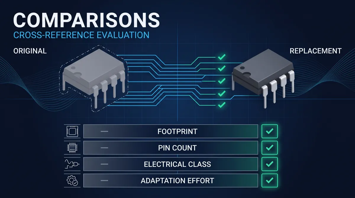
AMS1117 vs LM1117 vs LD1117: 3.3V LDO Regulator Comparison Guide
When designing power supply circuits for embedded systems, microcontrollers, and sensor interfaces, engineers frequently encounter three of the most ubiquitous low-dropout voltage regulators in the industry: the AMS1117, the LM1117, and the LD1117. These three-pin linear regulators all offer 3.3V fixed output variants and share compatible pinouts, making them seemingly interchangeable at first glance. However, the AMS1117 vs LD1117 comparison reveals significant differences in dropout voltage, thermal performance, load regulation, and quiescent current that can make or break a design depending on the application requirements.
This comprehensive comparison guide examines the technical specifications, real-world performance characteristics, and practical selection criteria for each regulator family. Whether you are designing battery-powered IoT devices, industrial control systems, or consumer electronics, understanding the nuanced differences between these seemingly similar components will help you make informed procurement decisions and avoid common design pitfalls.
Understanding LDO Regulator Fundamentals
Low-dropout (LDO) voltage regulators are essential components in modern electronics, providing stable output voltages from varying input sources. The AMS1117 vs LD1117 comparison starts with understanding what makes these devices fundamentally similar and where their architectural differences lie.
An LDO regulator operates by controlling the resistance of a pass element—typically a P-channel or N-channel MOSFET or a PNP transistor—to maintain a constant output voltage despite changes in input voltage or load conditions. The dropout voltage represents the minimum difference between input and output that the regulator can sustain while maintaining regulation. Lower dropout voltages enable more efficient operation, especially in battery-powered applications where every millivolt matters.
The AMS1117 family, manufactured by Advanced Monolithic Systems, provides a fixed 3.3V output with a typical dropout voltage of 1.1V at full load. The LM1117, originally developed by National Semiconductor (now part of Texas Instruments), offers a lower dropout of approximately 1.2V but with enhanced line and load regulation specifications. The LD1117, produced by STMicroelectronics, sits between these two with a typical dropout around 1V while emphasizing superior thermal performance and built-in protection circuits.
Understanding these baseline characteristics is crucial for engineers evaluating the AMS1117 vs LD1117 comparison for specific applications. The choice between these regulators impacts not only electrical performance but also PCB thermal management requirements, external component selection, and overall system reliability.
Electrical Specifications and Parameter Comparison
The AMS1117 vs LD1117 comparison requires a detailed examination of each device's electrical characteristics. The following table summarizes the key specifications across all three regulator families, enabling direct performance benchmarking.
| Parameter | AMS1117-3.3 | LM1117-3.3 | LD1117-3.3 | Units |
|---|---|---|---|---|
| Output Voltage | 3.3 ±2% | 3.3 ±1% | 3.3 ±1% | V |
| Dropout Voltage (typ) | 1.1 | 1.2 | 1.0 | V |
| Dropout Voltage (max) | 1.3 | 1.4 | 1.2 | V |
| Output Current | 800 | 800 | 800 | mA |
| Line Regulation | 0.2 | 0.035 | 0.1 | %/V |
| Load Regulation | 0.5 | 0.2 | 0.3 | % |
| Quiescent Current | 5-10 | 5 | 5-10 | mA |
| Ripple Rejection | 60 | 75 | 65 | dB |
| Operating Temp Range | -40 to 125 | -40 to 125 | -40 to 125 | °C |
Line regulation measures how well the output voltage maintains its value when the input voltage changes. The AMS1117 vs LD1117 comparison shows that the LM1117 leads with 0.035%/V typical line regulation, significantly outperforming the AMS1117's 0.2%/V specification. This makes the LM1117 preferable for applications with unstable or noisy input power sources, such as automotive systems or adapters with poor regulation.
Load regulation describes the output voltage variation as load current changes from minimum to maximum. The AMS1117 vs LD1117 analysis reveals that the LM1117 again demonstrates superior performance at 0.2% compared to the AMS1117's 0.5% specification. For circuits with rapidly changing loads—such as microcontroller-based systems with switching peripherals—this characteristic directly impacts system stability and requires careful consideration during component selection.
Ripple rejection capability determines how effectively the regulator attenuates input voltage noise and ripple. The AMS1117 vs LD1117 comparison shows the LM1117 achieves 75dB typical rejection, making it the preferred choice for power supply filtering in sensitive analog applications. The AMS1117 and LD1117 offer 60dB and 65dB respectively, which remains adequate for most digital circuits but may prove insufficient near radio frequency circuits or precision analog front-ends.
Dropout Voltage Analysis and Power Efficiency
Dropout voltage represents one of the most critical parameters in the AMS1117 vs LD1117 comparison, particularly for battery-powered applications where power efficiency directly correlates with device runtime. This section analyzes how each regulator's dropout characteristic impacts real-world performance.
The LD1117 achieves the lowest typical dropout voltage at approximately 1.0V, followed closely by the AMS1117 at 1.1V and the LM1117 at 1.2V. While these differences appear minimal—only 200mV separates the best from the worst performer—the practical implications become significant when operating near the minimum input voltage threshold.
Consider a 3.3V system powered from a lithium polymer battery with a nominal voltage of 3.7V. With the LD1117's 1.0V dropout, the system can operate until the battery discharges to 4.3V. The AMS1117's 1.1V dropout reduces this threshold to 4.4V, while the LM1117's 1.2V dropout demands 4.5V minimum. In a battery capacity context, this seemingly small 200mV difference can represent 5-10% additional usable capacity, translating directly to extended operating time.
Power dissipation analysis further illustrates why dropout voltage matters. At 500mA load current with a 5V input, all three regulators dissipate identical power (5V - 3.3V) × 0.5A = 0.85W. However, when the input voltage approaches the minimum required level, regulators with lower dropout can operate at higher efficiencies. The AMS1117 vs LD1117 comparison reveals that the LD1117's superior dropout performance enables more efficient operation across a broader input voltage range, reducing thermal management requirements and improving overall system efficiency.
Thermal considerations compound the dropout analysis. Higher dropout voltages force the regulator to dissipate more power for equivalent load conditions, raising junction temperatures and potentially triggering thermal shutdown in space-constrained designs. The AMS1117 vs LD1117 comparison shows that choosing a regulator with marginally better dropout characteristics can eliminate the need for external heatsinking or larger PCB copper areas, particularly in enclosed industrial enclosures or high ambient temperature environments.
Thermal Performance and Heat Dissipation
Thermal management represents a crucial design consideration when comparing AMS1117 vs LD1117 regulators for high-current applications. Linear regulators convert excess voltage into heat, and understanding thermal characteristics prevents reliability failures and ensures long-term system stability.
The thermal resistance from junction to ambient (θJA) depends heavily on the package type and PCB mounting configuration. All three regulator families typically come in SOT-223 and TO-252 packages, with θJA values ranging from 60°C/W for SOT-223 on minimal PCB pads to below 20°C/W with substantial copper plane heatsinking. The AMS1117 vs LD1117 comparison shows that actual thermal performance differences between manufacturers are minimal when using identical packages—the primary variation comes from thermal pad design and PCB layout practices.
Maximum junction temperature for all three regulators is typically 150°C, with thermal shutdown activating around 155-165°C. This leaves a comfortable margin for most applications, but designs must still account for worst-case scenarios including maximum ambient temperature, minimum airflow, and aging effects on thermal resistance.
Calculating safe operating conditions requires understanding the power dissipation relationship: PD = (VIN - VOUT) × IOUT. For a 3.3V regulator operating from a 5V supply at 500mA, power dissipation equals 0.85W. Assuming a junction-to-ambient thermal resistance of 40°C/W (typical for SOT-223 with moderate PCB heatsinking), the temperature rise equals 0.85W × 40°C/W = 34°C. If the maximum ambient temperature reaches 85°C, the junction temperature would reach 119°C—well within safe operating limits. However, the same calculation at 125°C ambient temperature yields 159°C, exceeding the thermal shutdown threshold.
The AMS1117 vs LD1117 thermal comparison reveals that at equal power dissipation levels, all three regulators exhibit similar thermal characteristics. The real design advantage comes from selecting a regulator with lower dropout voltage to reduce power dissipation in the first place. A system operating at the edge of dropout can potentially save 100-200mW by choosing the LD1117 over the AMS1117—power that would otherwise become heat requiring thermal management.
Load and Line Transient Response
Dynamic performance characteristics differentiate these regulators in ways that static specifications cannot capture. The AMS1117 vs LD1117 comparison must consider how each device responds to rapid changes in load current and input voltage, as these transient behaviors directly affect output voltage stability.
Load transient response measures how quickly the output voltage recovers after a sudden load change. When a microcontroller transitions from idle to active processing, drawing additional current from the regulator, the output voltage initially drops before the feedback loop corrects it. The overshoot and recovery time depend on the regulator's bandwidth, output capacitance, and compensation network design.
The AMS1117 family typically exhibits output capacitance requirements of 22µF minimum for stability, with response times in the 50-100µs range for moderate load steps. The LM1117 requires similar capacitance but achieves faster transient recovery due to its more sophisticated feedback architecture. The LD1117, designed with STMicroelectronics' optimized compensation, provides comparable or slightly better transient response while maintaining stability with ceramic capacitors as low as 10µF.
Line transient response characterizes output voltage stability when the input voltage changes rapidly. Automotive applications, in particular, require excellent line rejection of transients from the vehicle electrical system. The AMS1117 vs LD1117 comparison shows the LM1117 leading with 75dB ripple rejection, which directly correlates to better attenuation of input voltage perturbations.
For IoT devices and sensor systems, output voltage stability during load transients prevents erratic behavior, brown-out conditions, and data corruption. The AMS1117 vs LD1117 evaluation should include oscilloscope measurements of the actual transient response in the target application, as datasheet specifications alone may not capture real-world performance with specific load profiles and PCB parasitics.
Application Circuits and External Component Selection
Successful implementation of AMS1117, LM1117, or LD1117 regulators requires careful selection of external components, particularly input and output capacitors. This section provides guidance for achieving optimal performance in the AMS1117 vs LD1117 comparison context.
Input capacitors serve multiple functions: filtering high-frequency noise, providing surge current during transient loads, and stabilizing the regulator's internal reference. All three regulator families require input capacitance for stability, with datasheets typically recommending 10µF minimum. Ceramic capacitors (X5R or X7R dielectric) provide excellent high-frequency filtering and small physical size, making them the preferred choice for modern compact designs. Electrolytic capacitors may be necessary for applications with high RMS current requirements or extended cable runs from the power source.
Output capacitor selection is more critical and varies between families. The AMS1117 requires a minimum of 22µF with ESR between 0.1Ω and 1Ω for stability—tantalum or electrolytic capacitors typically satisfy this requirement, while ceramic capacitors may cause instability due to their very low ESR. The LM1117 similarly requires output capacitance with specific ESR bounds, and the datasheet provides detailed ESR vs. output current charts. The LD1117 offers more flexibility, accepting ceramic capacitors with proper selection, though it still benefits from tantalum or electrolytic capacitors for optimal AC performance.
PCB layout significantly impacts regulator performance regardless of which family you select in the AMS1117 vs LD1117 comparison. Input capacitors should be placed as close as possible to the input pin, with short wide traces minimizing loop inductance. Ground connections should use dedicated vias to the ground plane rather than shared traces. Output capacitors require similar attention, placed near the output pin with short connections to the ground plane.
For applications requiring very low noise, adding a secondary LC filter after the LDO can provide additional attenuation. However, this approach reduces available headroom and complicates stability analysis—trade-offs that must be carefully evaluated against the noise requirements of sensitive analog circuits.
Protection Features and Reliability Considerations
Built-in protection circuitry distinguishes production-grade regulators from bare regulator cores. The AMS1117 vs LD1117 comparison reveals different approaches to protection features that impact system reliability and field longevity.
All three regulator families include thermal shutdown protection that disables the pass element when junction temperature exceeds approximately 155°C. This self-protective behavior prevents permanent damage during overload conditions but should not be relied upon for normal operation—thermal shutdown indicates inadequate thermal design that requires correction.
Current limiting protects against short-circuit failures. The AMS1117 family typically implements foldback current limiting, reducing maximum output current during output short conditions to approximately 200-400mA. The LM1117 provides similar protection with slightly higher short-circuit current capability. The LD1117 includes enhanced current limiting with faster response time, reducing peak fault currents that could stress downstream components.
Reverse polarity protection varies by family and application. While none of these regulators include explicit reverse polarity protection circuitry, the body diode of the internal pass element provides some inherent protection when input voltage is reversed. However, prolonged reverse bias can damage the device, and explicit protection circuitry (diodes, MOSFET switches) should be considered for applications with connector reversal risk.
The AMS1117 vs LD1117 comparison for protection features shows that STMicroelectronics' LD1117 includes additional refinement with improved ESD protection (typically 2kV HBM) and enhanced ruggedness for demanding environments. This makes the LD1117 slightly more suitable for industrial and automotive applications where voltage transients and ESD events are common.
Package Options and PCB Footprint Compatibility
Physical packaging options influence thermal performance, PCB layout flexibility, and assembly costs. All three regulator families share common package options, enabling direct footprint compatibility in most designs.
SOT-223 packages offer a good balance of thermal performance and board area. With a 3.5mm × 6.5mm body and four pins (one tab connected to ground), SOT-223 regulators can dissipate 1-2W with appropriate PCB heatsinking. The tab provides a thermal path to the PCB, and multiple vias to the ground plane improve heat spreading. The AMS1117 vs LD1117 comparison shows all three families commonly available in SOT-223, making package selection independent of regulator choice.
TO-252 (DPAK) packages provide slightly better thermal performance through a larger exposed pad and improved package height characteristics. The TO-252 footprint uses corner pins rather than the linear arrangement of SOT-223, requiring different PCB footprints but offering similar functionality. For designs requiring hand soldering or manual assembly, TO-252 packages may be easier to work with due to their larger size.
SOT-89 packages offer a middle ground with three pins and good thermal performance through the package's header-style construction. While less common for high-current applications, SOT-89 provides a compact solution for lower-power 3.3V rails where board space is at a premium.
Pinout compatibility exists across all three families when using the same package type. The standard three-pin configuration (IN, GND, OUT) allows dropping in replacement of any family without PCB modifications, facilitating easy substitution during prototyping or production changes. However, the AMS1117 vs LD1117 comparison notes that some second-source manufacturers may have slightly different pin sequences—always verify pin assignments before assembly.
Price Analysis and Supply Chain Considerations
For procurement teams evaluating the AMS1117 vs LD1117 comparison, unit pricing and supply chain availability significantly impact component selection. While technical performance remains paramount, real-world sourcing considerations often determine final component choices.
The AMS1117 family enjoys the lowest typical pricing, often 30-50% cheaper than branded alternatives from Texas Instruments or STMicroelectronics. This price advantage stems from multiple Asian semiconductor manufacturers producing AMS1117-compatible devices. However, this cost saving comes with trade-offs: wider tolerance bands, less stringent quality control, and potentially inconsistent performance across manufacturers using the same datasheet specifications.
The LM1117 commands premium pricing reflecting National Semiconductor's (now TI) engineering heritage and quality standards. At typical volumes, LM1117 units cost approximately 2-3× the AMS1117 equivalent. This premium buys tighter output voltage tolerance (1% vs. 2%), superior line and load regulation, and more consistent performance across temperature ranges. For applications where these specifications matter, the LM1117 provides genuine value.
The LD1117 occupies a middle price position, typically 10-20% more expensive than the AMS1117 while offering performance specifications closer to the LM1117. STMicroelectronics' quality reputation and European manufacturing add value for industrial and automotive supply chains, where traceability and consistent quality matter more than marginal cost savings.
Supply chain resilience should factor into the AMS1117 vs LD1117 decision. TI and STMicroelectronics maintain robust distribution networks with multi-source availability. AMS1117 devices, while widely available, may come from smaller distributors with less reliable long-term availability commitments. For production volumes where second-sourcing matters, the LM1117 and LD1117 families offer better supply chain risk mitigation.
Industry Application Case Studies
Understanding how each regulator performs in real applications provides context for the technical specifications. This section examines typical use cases where the AMS1117 vs LD1117 comparison yields clear recommendations.
Consumer electronics and hobbyist projects frequently employ the AMS1117 due to its low cost and widespread availability. Arduino-compatible boards, USB-powered projects, and budget-conscious consumer devices benefit from the AMS1117's price point. However, designers must account for its inferior load regulation when powering loads with variable current draw, such as microSD cards, wireless modules, or LED indicators.
Industrial automation applications favor the LM1117 or LD1117 for their superior regulation and reliability characteristics. PLC input stages, sensor power rails, and industrial communication interfaces (RS-485, CAN) benefit from tight output voltage tolerance despite input voltage variations from long cable runs or shared power distribution. The LM1117's 75dB ripple rejection also helps filter noise from switching power supplies commonly found in industrial environments.
Battery-powered IoT devices require careful analysis of the AMS1117 vs LD1117 trade-offs. While the AMS1117's marginally lower cost matters in high-volume production, the LD1117's superior dropout voltage directly translates to extended battery life. For coin-cell powered sensors, BLE modules, or low-power wireless applications, the LD1117's efficiency advantage can significantly extend replacement intervals or enable smaller battery packages.
Automotive electronics demand the highest reliability standards, typically selecting the LD1117 or LM1117 over generic AMS1117 alternatives. The LD1117's enhanced ESD protection and automotive temperature grade availability make it suitable for under-hood applications, instrument clusters, and body control modules. These applications require full temperature range operation and robust protection against load dumps and transients.
3.3V vs 5V Applications: Choosing the Right Output
While all three regulator families support multiple output voltage options, the 3.3V variant represents the most common selection for modern digital electronics. This section clarifies when 3.3V regulators specifically suit your application versus alternative configurations.
The 3.3V voltage level has become an industry standard for low-power digital logic, microcontrollers, and memory devices. Modern ARM Cortex-M microcontrollers (STM32, NXP LPC, Nordic nRF52 series) operate natively at 3.3V, as do most sensors, display modules, and communication transceivers. Using a 3.3V LDO to power these components eliminates level-shifting complexity and ensures optimal signal integrity.
The AMS1117 vs LD1117 comparison for 3.3V applications reveals particular considerations for battery-powered devices. Lithium-ion batteries with single-cell chemistry provide 3.6-4.2V nominal voltage, making the dropout voltage margin critical. A 3.3V regulator with 1.0-1.2V dropout leaves only 2.4-3.2V headroom from a fully discharged battery, limiting usable capacity. For such applications, lower dropout alternatives like the MCP1700 (255mV dropout) or TPS7A02 (200mV dropout) may merit consideration despite higher cost.
USB-powered applications commonly use 3.3V LDOs to derive logic power from the 5V USB supply. The AMS1117, LM1117, and LD1117 all work in this configuration, with the LD1117's slightly better dropout providing marginally higher efficiency. However, USB-powered designs must consider inrush current limits and should include appropriate input capacitance to meet USB specification requirements.
Selection Guide: Matching Regulator to Application
Translating the AMS1117 vs LD1117 comparison into actionable design decisions requires matching technical characteristics to application requirements. This section provides a systematic selection framework for engineers facing component selection challenges.
For budget-sensitive consumer applications where absolute performance specifications matter less than cost, the AMS1117 remains a viable choice. Designs powering stable loads with moderate current requirements and adequate thermal margins can successfully use the AMS1117 while enjoying significant cost savings. The key is honest assessment of actual performance requirements versus datasheet specifications.
For applications requiring tight output voltage tolerance and excellent line/load regulation, the LM1117 justifies its premium pricing. Test and measurement equipment, precision sensor interfaces, and calibration circuits benefit from the LM1117's superior regulation specifications. Its 75dB ripple rejection also makes it the preferred choice for mixed-signal designs with sensitive analog sections.
For balanced performance with industrial quality standards, the LD1117 offers an attractive middle ground. The LD1117 provides better-than-AMs1117 regulation with pricing closer to the AMS1117 than the LM1117, making it an excellent default choice when requirements are not firmly established. Its slightly better dropout voltage also benefits battery-powered applications.
For automotive and demanding industrial environments, only the LD1117 with appropriate automotive grades (AEC-Q100 qualification) should be considered. Standard commercial-grade versions of any family may not meet the environmental and reliability requirements of these applications.
Common Design Mistakes to Avoid
Learning from others' experiences prevents costly errors in LDO regulator selection and implementation. This section catalogs common pitfalls in the AMS1117 vs LD1117 comparison context that engineers should avoid.
Insufficient input capacitance ranks among the most frequent LDO design errors. Some designers, seeking to minimize component count, omit input capacitors or use values below datasheet minimums. This causes oscillation, poor transient response, and excessive ripple on the output. Always include the recommended input capacitor, typically 10µF minimum, placed as close as possible to the input pin.
Output capacitor selection errors cause instability with AMS1117 and some LM1117 variants. Using ceramic capacitors with very low ESR can violate the minimum ESR requirements, causing high-frequency oscillation even when output voltage appears stable on a multimeter. When in doubt, use the output capacitor types explicitly recommended in the datasheet rather than assuming lower ESR is always better.
Inadequate thermal design manifests as intermittent operation, premature failure, or unexpected thermal shutdown. The AMS1117 vs LD1117 comparison shows that at 500mA with 5V input, all these regulators dissipate over 800mW—sufficient to cause thermal issues without proper PCB heatsinking. Calculate worst-case junction temperature during design, not typical conditions.
Ignoring dropout voltage margins leads to unexpected behavior as batteries discharge or input voltage sags under load. Designing for worst-case input voltage minus minimum dropout plus maximum output current creates a margin for safe operation. Using the AMS1117 or LM1117 in applications with marginal headroom invites dropout-related system failures.
Datasheet Interpretation and Specification Limits
Datasheets contain both typical and maximum/minimum specifications, and understanding the difference is essential for robust design. The AMS1117 vs LD1117 comparison requires careful interpretation of these values to avoid over- or under-designing the power supply.
Typical specifications represent mean or median values measured under standard conditions (25°C, nominal input voltage). These values should not be used for design calculations, as they represent best-case scenarios. The AMS1117's typical dropout of 1.1V can actually reach 1.3V maximum under worst-case conditions—design your circuit assuming the maximum value, not the typical.
Minimum and maximum specifications define the bounds of guaranteed performance. All production units must meet these specifications across the entire operating temperature range and process variation. When comparing AMS1117 vs LD1117 datasheets, pay attention to whether specifications are guaranteed minimum/maximum or merely typical.
Output voltage tolerance includes both the initial accuracy and the drift over temperature and time. The AMS1117's ±2% tolerance (versus ±1% for LM1117 and LD1117) may or may not matter depending on your load's voltage sensitivity. A 3.3V regulator with 2% tolerance can produce anywhere from 3.234V to 3.366V—a range that exceeds the tolerance of some precision analog circuits.
Ripple rejection specifications typically apply at specific frequencies (100Hz or 120Hz for power line harmonics) and may degrade at higher frequencies. The AMS1117 vs LD1117 comparison shows 60-75dB rejection at 120Hz, but this performance may not extend to the kilohertz and megahertz ranges where switching power supply noise appears. For filtering switching noise, additional filtering stages may be necessary regardless of datasheet ripple rejection numbers.
Quality Grades and Automotive Qualifications
Component quality grades significantly impact reliability and performance consistency. The AMS1117 vs LD1117 comparison must consider how different manufacturers segment their product families into quality tiers.
Commercial grade components, the most common offering, are specified for operation from 0°C to 70°C and manufactured to standard quality levels. These parts suit most consumer and industrial applications but may not meet the reliability requirements of safety-critical or long-lifetime applications. The AMS1117 is almost exclusively available in commercial grade, limiting its suitability for demanding environments.
Industrial grade parts extend temperature range to -40°C to +85°C and often include enhanced screening or burn-in procedures. The LM1117 and LD1117 are commonly available in industrial grades, providing better temperature performance and more consistent specifications across units.
Automotive grade components (AEC-Q100 qualified) undergo additional testing for temperature cycling, humidity resistance, and electromigration reliability. These parts are mandatory for automotive safety systems and increasingly required for industrial applications where failure could cause injury or significant economic loss. The LD1117 and LM1117 families offer automotive-grade variants; the AMS1117 generally does not.
Medical and military grade components exist but represent specialized offerings not typically compared in the AMS1117 vs LD1117 context. These applications require different regulator architectures optimized for ultra-low noise, high precision, or extreme environmental performance.
Comparative Summary and Final Recommendations
After comprehensive analysis of the AMS1117 vs LD1117 comparison across all relevant dimensions, clear patterns emerge that guide practical selection decisions. This section synthesizes the findings into actionable recommendations.
The AMS1117 family occupies the budget segment, offering acceptable performance at the lowest cost. Its 2% output voltage tolerance and 0.2%/V line regulation may prove insufficient for precision applications, but for cost-sensitive consumer products, hobby projects, and non-critical auxiliary rails, the AMS1117 delivers adequate performance. Just ensure your thermal design accounts for 1.1V dropout and plan for the 0.5% load regulation variation when loads vary significantly.
The LM1117 represents the precision option, offering the tightest specifications and best ripple rejection. Its 1% tolerance and 0.035%/V line regulation make it ideal for analog circuits, sensor interfaces, and applications where output voltage accuracy directly impacts system performance. The 75dB ripple rejection also benefits designs near switching power supplies or motor drivers.
The LD1117 provides the best overall balance for most applications. With 1% tolerance, 0.1% line regulation, and 1.0V dropout, it offers LM1117-like performance at AMS1117-adjacent pricing. The LD1117's slightly better dropout voltage also benefits battery-powered applications, and STMicroelectronics' quality reputation adds supply chain confidence.
For new designs where requirements are still evolving, starting with the LD1117 provides the most flexibility. Its balanced specifications accommodate most applications, and the straightforward upgrade path to LM1117 exists if precision requirements emerge later. The AMS1117 is best reserved for high-volume cost-sensitive designs where thorough characterization confirms its suitability.
The ultimate choice between AMS1117 vs LD1117 depends on your specific application requirements, volume projections, and reliability expectations. Use this guide to match technical characteristics to your needs, then verify availability and pricing from your preferred distributors before finalizing the design.
Not sure which sensor fits your project?
Talk to our mmWave application engineers for a free consultation.
Specify your hotel project with our engineers
Send your room count, ceiling type, and protocol preference. We will return a sample plan and quote within 24 business hours.
- Move from general guidance into a product or application discussion.
- Use RFQ when pricing, drawings, MOQ, or launch timing needs structure.
- Keep a direct contact path visible for fast clarifications and handoff.