ULN2003 Alternatives: The Darlington Transistor Array Guide
Darlington transistor array alternative guide: how to find an ULN2003 or ULN2803 equivalent, comparing channels, drive current, output voltage, and package.
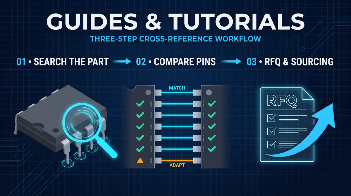
A Darlington transistor array alternative is the question that follows the most common driver solution in electronics, because the Darlington array is how signals drive inductive and high-current loads, and the ULN2003 is the part that nearly every board uses for the job. A Darlington transistor array is an integrated circuit that packs several Darlington transistor pairs into one package, each pair combining two transistors to amplify a small input signal into a high-current, open-collector output, and the ULN2003 is the 7-channel version that drives relays, motors, solenoids, LEDs, and stepper coils from the small logic pins of a microcontroller. The alternative question is answered in one way by the family, because the Darlington array's function and pinout are reproduced across a field of vendor parts, and answered carefully in another, because the substitution has to respect the channels, the current, the voltage, and the on-chip flyback diodes that this guide reads. This guide explains what a Darlington array does, how the ULN2003 and its 8-channel sibling the ULN2803 fit, how to find their equivalents, and how to substitute one safely, so the driver block is chosen on the evidence.
The guide also reads the question the community actually asks, because the SERP for a Darlington array alternative surfaces the real engineering inquiries. The question "What is the IC equivalent of the ULN2003?" is a daily one, and the answer is the family map, the MC1413, the TD62083, the domestic ULN2003 parts, and the 8-channel ULN2803, and this guide gives the map with the checks that make it safe. The Darlington array is one of the friendliest parts in the catalog to replace, because the function and the pinout are standardized and the family is deep, and the method that keeps the replacement safe is the same three-layer review this site applies everywhere, the package, the pins, and the electrical behavior, plus the special feature that defines the part, the flyback diode.
What a Darlington Transistor Array Does
A Darlington transistor array is a digital-to-power interface in one package, and it is the part that lets a small logic signal switch a large load. Each channel of the array is a Darlington pair, two transistors connected so that the first amplifies the base current of the second, and the pair delivers a large current gain, so a few milliamps of input drives a few hundred milliamps of output. Each channel output is an open-collector, the transistor's collector brought out to the pin with the emitter grounded, so the channel sinks current from the load that connects from the positive supply through the load to the output pin, which is the classic low-side driver arrangement. The array also integrates the flyback diodes, the diodes across each output that clamp the inductive kickback when a relay or a motor coil turns off, which is the feature that makes the Darlington array the standard relay driver. The array's job, interface, amplify, switch, and clamp, is why the ULN2003 is everywhere, and the alternative must do the same job.
The two reference parts organize the array's world. The ULN2003 is the 7-channel Darlington array in the 16-pin package, the most common version that drives seven loads from seven logic inputs, and the ULN2803 is the 8-channel version in the 18-pin package for the eight loads. Both carry the same per-channel current and the same on-chip diodes, and the difference is the channel count and the package, which is the first fact of the alternative. The design that drives seven loads uses the ULN2003 and its equivalents, and the design that drives eight uses the ULN2803 and its 18-pin family, and the substitution reads the count before anything else. The Darlington array's popularity is the reason the alternative guide starts at the ULN2003, and the count is the map's first dimension.
How the ULN2003 drives relays and motors
The ULN2003 drives relays, motors, and solenoids through its open-collector channels and its on-chip diodes. To drive a relay, the load connects from the positive rail to the channel output, the channel's input connects to the logic pin, and when the logic goes high the Darlington pair turns on and sinks current through the relay coil, energizing it, and when the logic goes low the pair turns off and the coil's inductive kickback is clamped by the on-chip flyback diode. To drive a stepper motor, a pair of ULN2003 channels, or a dedicated ULN2003-based module, drives the motor's coil phases in sequence, and the array has the current and the diodes for the job, which is why the ULN2003 is the standard stepper driver. The output current per channel, the 500-milliamp class, and the open-collector arrangement are the parameters the load design reads, and the array's role is the interface that keeps the logic and the high-current world separate. The ULN2003's job is the reference the alternatives must match, and the load, the coil, the diode, and the current are the match's specifications.
The ULN2003 as the Darlington Array Reference
The ULN2003 is the reference Darlington array, and understanding its package, its pins, and its numbers makes every alternative concrete. The ULN2003 comes in the 16-pin package, the DIP-16 and the SOIC-16, with seven input pins and seven output pins, the ground, and the common-diode pin, and the pinout, input 1 to 7 on one side and output 1 to 7 opposite, is standardized across the vendor field. Each channel of the ULN2003 handles the 500-milliamp class of output current, works with an output voltage up to the 50-volt class, and accepts the TTL-compatible 5-volt logic input, which is why it drives directly from the microcontrollers and the logic. The common diode pin connects the cathode of the flyback diodes, letting the designer tie it to the positive rail for the clamp, and the diode integration is the feature that makes the ULN2003 a complete relay driver in one part. The numbers and the pins are the reference the alternatives are read against.
The ULN2003's popularity is also the reason its family is so deep, because the function and the pinout are reproduced by the vendors and the domestic manufacturers. The TD62083 and the MC1413 and the ULN2003 parts from the field share the 16-pin layout and the per-channel numbers, and the sourcing can move across the family on the same footprint and the same driver circuit. The reference part anchors the map, the vendor parts and the family versions ring around it, and the substitution reads the ring before the datasheet. The guide's method is to treat the ULN2003 as the reference and to read every alternative, the package, the pins, the channels, the current, the voltage, and the diodes, against it, which is the same discipline that every reliable substitution uses.
The 7-channel ULN2003 versus the 8-channel ULN2803
The 7-channel ULN2003 and the 8-channel ULN2803 are the two counts of the Darlington world, and the choice between them is a count decision. The ULN2003 in the 16-pin package drives seven loads, and it is the part of choice for a block with six or seven outputs, a 28BYJ stepper, a relay bank of four or seven, and a display driver of seven segments. The ULN2803 in the 18-pin package drives eight loads, and it is the part of choice for the block with eight outputs, a full port of eight, and the parallel driver banks. The per-channel specifications are the same, the 500-milliamp current class and the 50-volt output class and the on-chip diodes, so the selection between the two follows the count and the package, and a 2803 fills 8 and a 2003 fills 7, and neither substitutes for the other without the channel count and the footprint changing. The count is the first decision of the Darlington world, and the guide reads it before the specifications.
Key Specifications of a Darlington Array Alternative
The specification read of a Darlington array alternative covers the channels, the current, the voltage, the input, and the diodes, and it is the layer the family name does not fully state. The channels decide the count, the seven or the eight, and the alternative must match the number the design drives. The output current per channel, the 500-milliamp class of the ULN family, decides how much load the channel can sink, and a design that drives a load near the limit reads the current and the package temperature rather than the label. The output voltage, the 50-volt class, decides the rail the open-collector outputs can switch, and a design on a 12-volt or a 24-volt rail reads the rating against the rail and the load's flyback voltage. The input, the TTL-compatible threshold of the ULN family, decides whether the logic drives the array directly, and a design with an open-collector source or a different logic level reads the input requirements. The on-chip diodes, the flyback clamp, decide whether the array is a complete relay driver, and an alternative without them forces the external diodes. The four reads are the datasheet layer of the alternative, and they are the layer the load design checks.
The read also covers the electrical limits that protect the part and the load. The total power, the channel current times the saturation voltage times the channels, sets the package temperature, and the Darlington array dissipates the dropout of the saturated pair, which is higher than a MOSFET driver's, and the thermal read at the maximum channels keeps the array in its rating. The reverse and the transient, the flyback voltage and the inrush, are the conditions the diodes and the external protection handle, and the design reads the absolute maximum ratings against the worst case. The specifications are the shared ground of the family, and the substitution that changes a number, a lower current, a lower voltage, a missing diode, changes the load design, which is why the alternative is verified against the exact load rather than against the family name.
How the flyback diode matters in a Darlington array
The flyback diode is the feature that makes the Darlington array a complete driver, and it matters because the inductive load would destroy the channel without it. When a relay coil or a motor winding is turned off, the collapsing magnetic field generates the flyback voltage, a spike across the coil that can reach many times the supply, and without a clamp the spike drives the channel into its breakdown. The Darlington array integrates the clamp as the diode across each channel, tied through the common pin to the positive rail, so the turn-off spike currents through the diode instead of the transistor, and the array survives and the load switches cleanly. The alternative must carry the same diode integration, or the design must add the external diodes, which changes the board and the cost. The diode read is the special feature of the Darlington array, and it is the reason a substitution that drops the diode is a redesign in disguise. The diode is the array's protection, and the protection is the alternative's requirement.
How to Find Darlington Array Equivalents
Finding a Darlington array equivalent runs through the same channels as any component search, with the channel count and the package as the filters. The equivalent of the ULN2003 is found by the cross-reference, the distributor's alternative-part feature, the aggregation platform, or the dedicated cross-reference engine, and the search returns the family, the TD62083, the MC1413, and the domestic ULN2003 parts, which the datasheet review then filters by the channels, the current, the voltage, and the package. The 8-channel ULN2803 finds its own family the same way, the TD62064 and the vendor 2803s on the 18-pin layout. The search habit is the same habit the series has used, collect from more than one source, sort by trust tier, and verify against the datasheet, and the verification is the step that turns the family map from a candidate list into a decision. The Darlington family's depth makes the search friendly, and the discipline makes it safe.
The search also reads the functional neighbors, because the Darlington array has relatives with the same job and a different implementation. The logic-level MOSFET drivers and the relay-driver ICs with the protection and the input features, and the open-collector logic buffers, can replace a Darlington array in the designs where the drop, the speed, or the channel features matter, and the substitution reads the differences, the saturation drop, the switching speed, and the input interface, against the design. The MOSFET driver's lower drop and its faster switching often displace the Darlington in the new designs, while the Darlington remains the simple and the protected choice for the classic loads. The neighbors are the alternatives beyond the family, and the substitution reads them with the same three-layer review, which is the method that keeps the wider field safe.
The ULN2803 and the 8-channel alternative families
The ULN2803 and its family serve the eight-channel driver, and the alternatives ring around it the way they do the ULN2003. The ULN2803 in the 18-pin package reproduces the same per-channel numbers as the ULN2003, the 500-milliamp current class, the 50-volt output class, and the on-chip diodes, with eight channels instead of seven, and the vendor versions, the TD62064 and the domestic 2803s, share the 18-pin layout. The substitution within the 2803 family moves across the vendors on the same footprint, and the design that drives eight loads sources the 2803's ring the same way it sources the 2003's. The design that needs more than eight channels cascades or multiplies the arrays, reading the shared outputs and the total current, and the design that needs fewer stays with the 2003. The 8-channel family is the mirror of the 7-channel family, and the guide reads both under the same method, the count, the package, and the verified vendor.
Package Variants of the Darlington Array
The package variants of the Darlington array are the footprint half of the alternative, and the 16-pin and the 18-pin packages cover the common boards. The ULN2003's 16-pin package appears as the DIP-16 for the through-hole world, the SOIC-16 for the surface-mount production, and the SOP variants that the vendors and the domestic parts use, and the pinout, seven inputs opposite seven outputs with the ground and the common diode pin, is reproduced across the variants. The ULN2803's 18-pin package follows the same story, the DIP-18 and the surface-mount variants with the eight channels on the wider layout. The alternative must match the footprint the board has laid out, because a board with an SOIC-16 pattern cannot mount a DIP-16 without an adapter, and the substitution keeps the package constant while the vendor and the family are traded. The package read is the mechanical contract of the alternative, and it is the first fact the schematic resolves.
The package variants also carry the thermal story, because the Darlington array's heat follows the channel count and the package's ability to shed it. The SOIC-16 in its surface-mount form sheds the heat through the leads and the board copper, and the DIP-16 in its through-hole form through the leads and the optional socket, and a design that runs several channels near the current limit reads the package's thermal path and the board's copper area rather than the family name. The SOIC-16 with the generous copper runs more channels than the same part on a minimal pad, and the layout of the copper under the package is part of the driver's thermal design. The package and the footprint are therefore the physical half of the alternative, and the thermal read completes the half, which is the discipline that keeps a multi-channel array from cooking in a dense board. The package variant is the same function in a different physical contract, and the substitution reads the contract before the vendor.
How to Test a Darlington Array Replacement
Testing a Darlington array replacement is the referee that the load design demands, and it runs the same staged sequence as every substitution. Mount the replacement on the board that held the original, and drive each channel with the same input the design uses, the logic level and the resistor value, and measure the output saturation voltage at the design's load current, because the Darlington's drop in saturation is the loss the load pays. Drive the real load, the relay, the motor, or the LED bank, and confirm each channel switches it on and off as the original did, with the correct timing and the correct state. Exercise the flyback, turning the inductive load off repeatedly and confirming the on-chip diode clamps the kickback and the channel survives, because the diode is the protection the load's turn-off depends on. Run the thermal pass, the maximum channels at the maximum load and the ambient, and confirm the package stays inside its junction rating. The test converts the candidate's datasheet into the design's evidence, and a replacement that passes is the replacement the board can trust, while one that fails is returned to the candidate list with the record.
The test also reads the interface and the timing that the firmware depends on. Confirm the input thresholds accept the logic levels the design drives, the TTL-compatible 5-volt input of the ULN family against the microcontroller's output, and confirm the switching speed, the turn-on and the turn-off time, fits the design's update rate, because a faster or a slower channel changes the relay timing and the stepper sequencing. Confirm the channel isolation and the cross-talk, where the design runs adjacent channels hard, and confirm the common diode pin is wired as the datasheet's application, tied to the positive rail, so the flyback clamp works. The interface and the timing reads complete the bench test, and the recorded results, the saturation voltages, the load behavior, the flyback pass, and the thermal log, are the evidence that moves the replacement to production. The Darlington replacement is tested against the load, and the load is the referee, which is the honest method the guide applies throughout.
When to Substitute a Darlington Array and When Not
The substitution of a Darlington array is the right move within the family and the careful move across the implementation, and the guide's limits are the same as every substitution's. Substitute within the ULN2003 and the ULN2803 families, the vendor ring and the pin-compatible equivalents, when the supply, the price, or the second source demands it, because the family preserves the board and the driver circuit. Substitute across to the MOSFET drivers and the neighbors when the design can accept the interface and the protection changes, with the full three-layer review and the load test. Do not substitute without reading the channels, the current, the voltage, and the diode, because a seven-channel board cannot be served by an eight-channel footprint, and a load at the current limit cannot be served by a lower-rated channel. And verify the bench, the load, the temperature, and the flyback, before the volume, because the Darlington's job is the load, and the load is the referee. The substitution is friendly within the family, and the discipline is the limit.
The response to a substitution limit is the standard source, substitute, or redesign. Source the original where it is available, substitute the verified family member where the count and the footprint match, and redesign the load interface around the MOSFET driver or the higher-current part where the current, the drop, or the speed demands it, recording the decision with the evidence. The Darlington array, being deep and standardized, rarely reaches the redesign for the classic loads, and the substitution is usually the answer. The limit is the count and the load interface, and the method that checks them is the method this guide provides, which is the working discipline this site applies to every part it sources and replaces.
Worked Example: Driving a Relay and a Stepper with the ULN2003
Driving a relay and a stepper with the ULN2003 is the worked example that shows the Darlington array in its natural jobs, and the numbers are the design's first read. A 5-volt relay coil that draws 70 milliamps sits comfortably inside the channel's 500-milliamp class, and the wiring is the classic low-side driver: the coil connects from the positive supply to the channel output, the input connects to the logic pin through the series resistor, and the common diode pin connects to the positive rail so the on-chip flyback diode clamps the coil's kickback on the turn-off. The input current is the second read, because the ULN2003 carries an internal base resistor in the kilohm class that sets the drive level, and a 5-volt logic input sinks the milliamps that the internal resistor allows, which is more than enough to saturate the output. The logic at a higher voltage, a 12-volt logic bus, needs the series resistor to limit the input current into the internal base resistor, and the datasheet's input section gives the resistor by the logic voltage. The relay's coil current, the logic drive, and the diode connection are the three numbers of the classic relay driver, and the ULN2003 carries all three in one part.
The stepper case extends the example to the multi-channel array. A 28BYJ-48 type 5-volt stepper draws a few hundred milliamps per phase, and the phases are driven in sequence from four of the ULN2003's channels, which is exactly the ULN2003 module that the market sells for the job. The sequence steps the four outputs high in turn, the stepper's windings magnetize and the motor advances a step, and on each transition the on-chip diodes clamp the winding's kickback. The design reads the phase current against the channel's rating and the total dissipation, especially when two phases are energized at once, and it powers the array and the stepper from an adequate supply. The worked example shows the counted and the current-rated face of the Darlington array, and it is the face the relay banks, the solenoid drivers, and the stepper chains all share, which is the practical proof of the part's place in the driver world.
The input-series-resistor calculation for the ULN2003
The input-series-resistor calculation for the ULN2003 starts with the internal base resistor that the part already carries, and the designer sizes the external resistor only where the logic demands it. The internal resistor sets the input current at a given logic voltage, and the output saturates with a few milliamps of input, so a 3.3-volt or a 5-volt logic output drives the ULN2003 directly with no resistor. A logic at 12 volts, or a supply whose input level must be limited, adds the series resistor that keeps the input current inside the part's rating, the resistor value being roughly the logic voltage minus the internal junction drops divided by the desired current minus the internal resistor's contribution. The practice is to read the datasheet's input-characteristics table at the logic level and size the resistor where the table says to, rather than to assume that a series resistor is always required, which is the small calculation the relay example demonstrates.
How to Build a Driver Block Around the Array
Building a driver block around the Darlington array is the wiring and the sizing half of the design, and it runs a consistent sequence. Wire the channels of the array to the loads, the outputs to the low ends of the loads with the loads' high ends on the positive rail, and the inputs to the logic via the series resistors where the logic requires them. Connect the common diode pin to the positive rail, because that connection is the flyback clamp's path, and connect the ground pins to the logic ground and the array's own ground near the returns. Add the decoupling, the bulk and the ceramic capacitors on the array's supply, because the switched loads draw the current in steps and the supply sag shifts the logic and the timing. The block is complete when the loads are wired, the diodes are tied to the rail, and the supply is decoupled, and the block is the same whether the loads are relays, solenoids, steppers, or LED banks.
The sizing that completes the block follows the dissipated power, which the Darlington pair's saturation voltage drives. The output saturation of a Darlington pair carries the two base-emitter drops of the stacked transistors, so the saturated output drops roughly a volt or more of the rail across the channel, and the total dissipation is the saturation voltage times the current times the number of active channels. A seven-channel array driving a few hundred milliamps on each active channel at the volt-class saturation dissipates a couple of watts, which the SOIC-16 with the board copper sheds and the marginal layout does not, so the power read sets the copper and the derating. The driver block is the wiring plus the sizing, and the sizing is the reason a multi-channel array needs the copper that the single-channel breadboard forgets, which is the design discipline the worked example and the thermal read together deliver.
Measuring and Troubleshooting the Driver Block
Measuring the Darlington driver block on the bench is the confirmation that the channels switch and the flyback holds, and it runs a short sequence. Drive each input in turn with the logic level the design uses and measure the output, the open-collector output pulling low when the channel is on, and measure the saturation voltage at the design's load current, the volt-class drop that the datasheet and the Darlington pair dictate. Switch the inductive load, a relay or a solenoid, and watch the output on the scope during the turn-off, the flyback spike clamped by the on-chip diode to the rail rather than allowed to runaway, which is the protection that the common diode pin connection enables. Measure the switching speed, the turn-on and the turn-off time, against the design's update rate, and the temperature of the package at the maximum active channels, and record the results beside the design values. The measurement is the referee of the driver block, and the record is the evidence that the block drives the load safely.
The troubleshooting list for the Darlington driver covers the failures that a new board meets. If a channel never switches, check the input, the series resistor, the logic level, and the soldering of that channel's pins, and check the channel itself by driving it directly, because a dead channel is a failed part rather than a wiring fault. If the relay or the load never releases, or the part dies after the first switch, check the common diode pin, a floating diode pin leaves the flyback unclamped and the output destroys itself on the first inductive turn-off, which is the classic failure of a mis-wired array. If the outputs all stay high or the logic floats, check the ground returns and the pull-downs on the inputs. If the package overheats, read the dissipation and the copper at the maximum channels. The troubleshooting list is the practical bookend to the driver block, and it is the checklist that keeps the array driving its loads for the life of the board.
The Input Interface: Series Resistors and Logic Levels
The input interface of the Darlington array is the bridge between the logic and the power, and the ULN2003's input is designed to sit on that bridge. The part is TTL-compatible, its input threshold and its internal base resistor sized for the classic logic levels, so a 3.3-volt or a 5-volt logic output drives it directly. The 3.3-volt logic drives the array because the threshold is low enough and the internal resistor yields enough base current at 3.3 volts, which is the common microcontroller interface, and the 5-volt logic drives it the same way. A logic at a higher voltage adds the series resistor to limit the input current, and a logic with an open-collector output adds the pull-up that the open-collector needs. The input also benefits from the pull-downs on the floating inputs, so the array's channels stay off while the microcontroller boots and the logic pins float high-impedance, which prevents the loads from latching on at power-up. The interface read is the small half of the driver design, and it is the half that keeps the logic and the power worlds talking cleanly, which is the completion of the driver block that this guide has built. The return paths close the block, because the load current returns through the array's ground and the logic current returns through the same ground, and a common, well-sized ground plane between the two keeps the logic noise down while the loads switch, which is the layout detail that a noisy driver block usually comes back to. The array and the loads share that plane, and the discipline of one clean return path is what keeps the driver's switching from corrupting the logic that controls it.
ULN2003 Alternatives: The Sourcing View
The sourcing view of the Darlington array alternative is the practical close, and it is the same view as the rest of the family. A design that standardizes on the ULN2003 or the ULN2803 selects a family that every vendor and the domestic manufacturers reproduce, so the sourcing can move across the vendor field and hold two suppliers on the same board, which is the second-source depth that the market has always used. The qualification of the alternative runs the same review, the package, the pins, the channels, the current, the voltage, and the diode, and the bench test with the real load and the flyback, and the verified alternative is recorded beside the part in the BOM and the cross-reference. The Darlington array's standardization turns the alternative from a risk into a sourcing option, and the option is the value the whole guide delivers. A designer who reads the ULN2003 alternatives this way selects the channel count, the verified vendor, and the tested load, and the selection is the working answer that the schematic, the board, and the load all accept.
Not sure which sensor fits your project?
Talk to our mmWave application engineers for a free consultation.
Specify your hotel project with our engineers
Send your room count, ceiling type, and protocol preference. We will return a sample plan and quote within 24 business hours.
- Move from general guidance into a product or application discussion.
- Use RFQ when pricing, drawings, MOQ, or launch timing needs structure.
- Keep a direct contact path visible for fast clarifications and handoff.