How to Find a Pin-Compatible Replacement IC
How to find a pin-compatible replacement IC: compare pins, package and electrical specs from the datasheet, then source a drop-in part without a redesign.
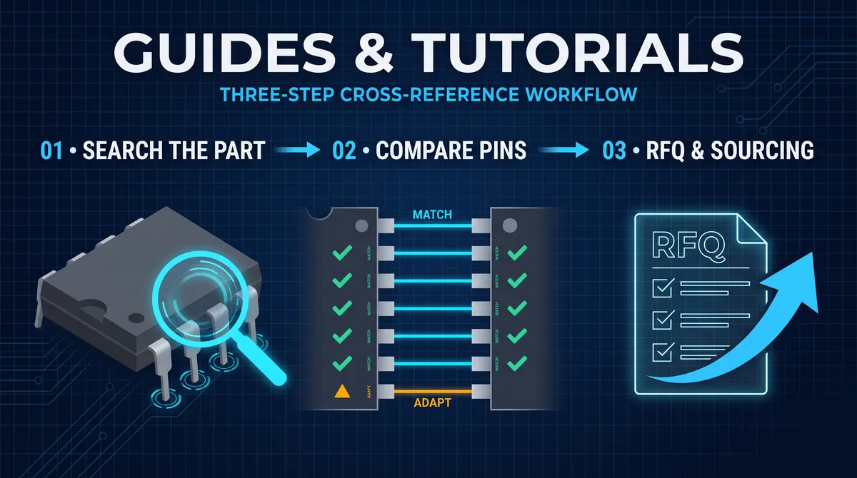
How to find a pin-compatible replacement IC is a question every design engineer, repair technician, and procurement buyer faces at some point, usually under time pressure. A part goes end-of-life, the original manufacturer raises the price beyond reason, a second supplier is needed for supply chain security, or a line that has been in production for a decade simply cannot get the exact chip it was designed around anymore. The word compatible is the key to the whole exercise: a pin-compatible replacement has the same physical pinout and the same package as the original, so it mounts on the same printed circuit board footprint without a board re-layout. That single property is what separates a practical swap from a redesign project, because re-laying out a board costs time, carries risk, and often requires new certifications. This guide walks through a repeatable method for finding a pin-compatible replacement, from reading the datasheet to validating a candidate with tools and physical testing, so the next time a part becomes unavailable the search does not have to start from zero.
The method in this guide is deliberately database-agnostic. It works whether you are searching an authorized distributor like DigiKey or Mouser, a BOM aggregation tool like Octopart or Findchips, a dedicated cross-reference search engine, or a pin-to-pin replacement supplier that stocks alternative parts. What all of those sources share is that they return candidates, and someone still has to judge whether a candidate is genuinely a drop-in. That judgment is a datasheet exercise, and the discipline of checking every pin and every electrical parameter before believing a cross-reference result is what keeps a replacement quiet instead of catastrophic. A pin-compatible part that shares the package and pin names but differs in maximum input voltage, output current, or switching frequency will often work at first glance and fail in quantity or at temperature, which is the most expensive way to discover a mismatch.
How to Find a Pin-Compatible Replacement IC from the Datasheet
A pin-compatible replacement IC is an integrated circuit that has the same pin functions on the same pin positions inside the same package as the original part, so it can be soldered onto the same PCB footprint and generally substituted without a board redesign. Engineers use the term interchangeably with pin-to-pin compatible, and the definition always involves three facts that must all be true: the physical package must be identical or footprint-identical, the power and ground pins must fall on the same positions, and the functional signal pins must carry the same functions even where the internal design differs. A candidate that matches the pins but not the package is not pin-compatible; a candidate that matches the package but assigns a different function to a pin is worse, because it appears identical and fails in the field. The reliable way to judge any candidate is to compare it against the original IC's datasheet pinout diagram and the candidate's own datasheet, pin by pin, from VCC through ground to every input and output. When the original datasheet is no longer available from the manufacturer, archive copies exist on datasheet aggregator sites, and the part number printed on the component body still identifies the exact variant to match. Reading for pin compatibility is the core skill of this whole process, and it is the step where most substitute failures are caught before they ever reach a test bench.
The standard flow for checking compatibility from the datasheet starts with pin counts. Count the pins on the original, then count the pins on the candidate; a 14-pin DIP part has no 16-pin surprise, and a shift between packages changes the exercise entirely. With equal pin counts, lay the two pinout diagrams side by side numbered from pin 1 and compare each position in sequence. Power pins, ground pins, and any unused no-connect pins usually match first because they are dictated by the package standard, which is why so many different manufacturers produce interchangeable parts for a classic pinout like the 78xx regulator series. The differences appear on the functional pins, where one vendor may put an output-enable where another puts an independent second input, or one datasheet labels a pin standby while the other labels it not connected. Any functional pin that differs, even one, downgrades the part from true pin-compatible to a candidate that needs a footprint, a jumper wire, or a trace cut, so the comparison must be exhaustive rather than a glance at the power pins. A quick and valuable habit is to record each pin's function in a table during the review, because that table becomes the future decision record for the whole team and the evidence a purchasing engineer can attach to a part change notice.
How to find a pin compatible replacement ic when the pinout is non-standard
When the chip is a standard catalog part, the pinout is documented everywhere and the comparison is fast. The harder question is how to find a pin compatible replacement ic when the device is a proprietary or application-specific part, a pull-up resistor, a transceiver with a vendor-specific pin arrangement, or a microcontroller where the datasheet lists dozens of GPIO positions. For those parts the same method applies but the search space needs to be wider, because the number of manufacturers who copy a proprietary pinout is smaller than the number who build to a public standard. Search the part number in a cross-reference database first, restrict to the exact package in the search filters, and then compare the candidate datasheet using the same pin-by-pin table. For microcontrollers, another powerful signal is the manufacturer's own alternate-device lists: a silicon vendor that sells a whole series on one pinout (as ST does with the STM32 line and GigaDevice does with the GD32 line) publishes migration notes that state exactly which devices are pin-compatible and what code changes the swap implies. Those migration notes are the highest-authority shortcut on the internet, and they resolve the compatibility question faster than any forum thread ever will.
What to record in the pin comparison table
A disciplined pin comparison table has one row per pin and four columns: the pin number, the original pin function, the candidate pin function, and a verdict of match, mismatch, or power-only. The power-only verdict covers the common case where the two parts both place VCC and GND on the same pins but one part adds a separate VCC pin for an internal regulator that the original did not expose. Print this table when the decision goes to a purchasing team, because a part number change on a production BOM under an ISO process is judged on evidence, and the table is the evidence. The table also prevents the single worst failure mode in substitution, which is the assumption that because the packages look alike the parts are identical. Manufacturers produce families of parts in the same package with deliberately different pin functions, and only a row-by-row review catches that. In practice, a completed table for a twelve-pin part takes under five minutes, and it converts a guess into a documented engineering decision.
Why Engineers and Procurement Teams Search for a Pin-Compatible Replacement
Engineers search for a pin-compatible replacement because it is the lowest-risk path out of a supply problem: no board redesign, no new firmware bring-up where it can be avoided, no re-approval of the whole assembly. Procurement teams search for the same phrase because a second source on the same footprint protects the production line from a single-vendor failure, a price shock, or a last-time-buy deadline that requires the supply chain to act fast. The most common trigger is an end-of-life notice, where the manufacturer declares a last-time-buy window and the buyer has to decide between stocking inventory and qualifying an alternative. Stocking years of inventory ties up capital and still ends at zero, so most teams prefer to qualify a pin-compatible replacement and keep the board design intact. The second most common trigger is component shortage, where even the originally made part is unobtainable at any price and the only question is what can be soldered in place instead. A part that can be swapped without touching the PCB layout keeps the whole assembly, its test fixtures, its idle-hour burn-in setup, and sometimes its regulatory approvals unchanged, which is why the same search phrase appears in every procurement team's playbook.
The value of a pin-compatible replacement is easiest to see when compared against the alternative. Redesigning a board to accept a differently pinned part means updating the schematic, re-routing the layout, re-spinning the prototype, re-validating EMC and signal integrity, and then re-running the manufacturing engineering work for the pick-and-place machine. That chain is measured in months and in real money, and it carries its own risk of introducing defects into a design that was already shipping. A pin-compatible swap collapses that chain back into a datasheet review, a sample test, and a qualification, because the physical interface to the rest of the board never changed. This is why the term drop-in replacement expresses the customer value in one word: the part drops into the existing board the way the original did, and everything downstream of that physical fact stays as it was. Where a true drop-in is not available, the compatibility hierarchy still guides the decision: pin-compatible and code-compatible microcontrollers come next, then footprint-compatible parts that need a jumper, and only at the bottom do you reach a redesign.
How to Find a Pin-Compatible Replacement IC in a Package That Fits
Matching the package is the second filter after matching the pins, and it is the filter that most search filters are built around. A package code like DIP-8, SOIC-8, TO-220, TSSOP-20, or SOT-23-5 determines the mechanical footprint the part occupies on the board, the solder paste footprint it uses, and the way the pick-and-place machine grips it, so a pin-compatible replacement must carry a package with the same pad layout. Two parts can have the same number of pins and completely different footprints: a SOIC-8 and a DIP-8 both have eight pins but one is a surface-mount part and the other is a through-hole part, and nothing about the pin count makes them interchangeable. The package comparison must therefore be done against the original board's pad geometry, which for an existing design is printed in the original part's footprint drawing or in the PCB design tool's library, and for a new design is simply whatever is already laid out. When a search tool asks for package type, pick the exact code or its body size variant (SOIC-8 is not automatically the same as SOP-8 from every vendor body outline), because the pad pitch and body width have to match the footprint that is already on the board.
Beyond the package code, three physical details decide whether the part literally fits. The first is the pin pitch, the distance between pin centers, which is fixed by the package standard for most codes but must still be confirmed for package families with both fine-pitch and wide-body variants. The second is the total lead geometry, because a gull-wing lead from one manufacturer can match a footprint designed for a J-lead from another manufacturer only if the pad accepts both. The third is the body height and orientation, which matter in enclosures with tight clearances and in boards where the polarity mark points into a specific corner. A package comparison done on these three details catches the classic false positives that pure pin-count searches produce. The reward for getting the package right is that the sample part mounts on the existing footprint cleanly, reflow behaves normally, and the first prototype test starts from a mechanical known state rather than from a mechanical question mark.
Compare the Electrical Specifications That Actually Matter for a Pin-Compatible Replacement
Pin matching and package matching establish that a part fits, but electrical matching is what establishes that it works, and it is the layer where most substitute failures actually live. The electrical comparison starts with the same parameters the original design was selected on: the operating voltage range and absolute maximum ratings, the output voltage and current or drive capability, the frequency or switching range, and the temperature grade. A linear regulator listed as pin-compatible with the 7805, for example, still has to deliver the same output voltage and current within the same input range, and a buck controller that is pin-compatible with a different part has to tolerate the same input voltage and switch at a compatible frequency for the same external inductor and capacitor values. The safest way to run this comparison is to line up the electrical characteristics tables from the two datasheets, row by row, and flag every parameter where the candidate is worse, where it is better but in a way that changes behavior, or where the value is simply not published. Parameters that are better are usually free advantages, but parameters that are better can still break a design when they change timing or output slew that the original circuit did not expect, so the review has to be a difference review, not a superiority review.
The practical electrical checks follow the function of the part. For a power component, verify input voltage limits, output regulation and accuracy, dropout or switching characteristics, efficiency where it matters for heat, and thermal resistance in the same package. For an op-amp or comparator, verify supply range, input offset voltage and bias current, gain-bandwidth product or slew rate, output swing, and whether the part is even a member of comparable families such as a single, dual, or quad configuration. For a logic chip, verify the logic family and speed grade, because 74 series parts differ across CMOS, TTL, and high-speed families, and the input thresholds and propagation delay must be acceptable to the surrounding circuitry. For an interface or driver part, verify the signal levels, the data rate, and the enable and fault pin behaviors. Throughout the review, keep the operating conditions realistic rather than ideal: the part has to work across the minimums and maximums of the product, not just at its nominal point, and the datasheet values that matter are the ones that apply over the operating temperature range the board is exposed to. A pin-compatible part that passes at 25 degrees but fails at the equipment's rated ambient temperature is a failure that logic and careful review will catch before production.
How to compare timing and frequency parameters during pin replacement
Timing parameters deserve their own treatment because they fail silently. A replacement oscillator, timer, memory, or logic part can have the identical pinout and supply a perfectly plausible signal that is still too slow, too fast, or incorrectly timed for the original circuit. Compare the published propagation delay, setup and hold time, recovery time, clock frequency maximum, rise and fall time, and programming or access time against the timing budget of the receiving circuit, not just against the original part's datasheet. A faster part can be as dangerous as a slower one: a shift register or memory that finishes a cycle sooner than the controller expects can complete a bus transaction out of sequence. Where the receiving circuit's timing budget is not documented, the accepted technique is to prototype with the candidate and stress the design at both clock edges and temperature extremes rather than trusting the datasheet alone. This is also the step where code compatibility enters for microcontrollers and digital parts, because a register map, an instruction set, or a peripheral configuration that differs even slightly will show up as timing-adjacent bugs that no pinout table can catch.
How to Find a Pin-Compatible Replacement IC Using Cross-Reference Tools
Cross-reference tools turn the manual search into a fast lookup, and knowing how to find a pin compatible replacement ic with them is now a core procurement skill. The tool landscape has three tiers worth understanding. Authorized distributors such as DigiKey and Mouser operate cross-reference and alternative-part features that are authoritative because the data comes from manufacturer relationships, and their parametric search lets a buyer filter by package, voltage, current, and function in one screen. Aggregation platforms such as Octopart and Findchips index millions of part numbers across hundreds of suppliers and return stock, price, and datasheet links together, which makes them the right place to start when the question is where to buy as much as what to buy. Dedicated cross-reference search engines such as X-refs and Z2Data and the independently hosted equivalent finders specialize in mapping one part number to its alternatives, and they are often the fastest way to find a pin-compatible candidate for an obscure part because their whole database is built on cross-reference records. Findchips.com and the equivalent finders of the component community are also the answer when the part is old enough that the manufacturer has removed it from the catalog.
Using these tools well means searching in the right order and trusting the source by tier. Start with the exact part number and the exact package in the search, pull the candidate list, and then filter by the electrical parameters the design depends on, rather than accepting the first alternative the tool shows. Across all three tiers the tool result is a candidate list, never a finished decision, so every result still goes through the pin table and the electrical table from the earlier sections. That is the discipline that separates a reliable substitution flow from a series of surprises. For the note that no tool is exhaustive, one practical habit is to search the original part number in at least two independent tools and compare the candidate lists, because each tool has gaps and the intersection plus the union both carry information. Where a tool offers an API or a bulk lookup, BOM-level checks against tens or hundreds of lines become quick enough to run as part of a standard supply review rather than an emergency response.
How to judge a manufacturer cross-reference table
The most authoritative cross-reference source is the alternate-part table published by the silicon manufacturer itself, and it is worth reading before any aggregated result. When a vendor states that part B is a direct replacement for part A, the statement comes from whoever designed B, and it usually includes the specific differences in a companion migration note. For microcontrollers this is the pinout and function compatibility matrix or the migration guide; for logic and analog parts it is the alternate listing or the recommended replacement note in the datasheet's ordering information. The judgment applies in both directions: a manufacturer table that lists a part as compatible is strong evidence, while a table that lists a part as not direct means the vendor is explicitly warning that the swap is more than a drop-in. Aggregated tools occasionally carry stale or one-directional records, which is why a claim from a cross-reference site is verified against the manufacturer's own note and against the two datasheets before a BOM is changed. The manufacturer cross-reference is also the best place to learn the family pattern, because once the pattern is understood, the next part in the same family can be compared without starting the search from scratch.
Verify Code and Firmware Compatibility for Microcontroller Replacements
Microcontrollers and digital signal controllers add a compatibility layer that analog and simple logic parts do not have, which is the code layer, and it decides most MCU substitutions in the end. A pin-compatible replacement MCU can be mechanically and electrically perfect and still fail the project because its flash base address, register map, peripheral set, or instruction set differs from the original, so the software that runs on the original crashes or silently misbehaves on the candidate. The cleanest example is the STM32 ecosystem, where the STM32F103 pin layout is deliberately shared across a wide family, and domestic manufacturers such as GigaDevice with the GD32F103 and Artery with the AT32F403A build parts that are not only pin-compatible but aim for software compatibility as well, documented through migration guides and register maps. Checking code compatibility is a three-part test: compare the core architecture and instruction set, compare the register map and the peripheral functions that the firmware actually uses, and then compile and run the firmware against the candidate on a reference board. A manufacturer migration note states which devices share the register level and what driver changes are needed, and that note is the first document to read before any MCU replacement is taken seriously.
The firmware verification itself is a controlled experiment with three layers of confidence. The first is a compile-and-link check, which proves the toolchain accepts the target device and resolves its startup and vector tables. The second is a peripheral bring-up test that exercises every module the firmware drives, including the clock tree, GPIO ports, timers, communication peripherals, and interrupts, comparing behavior and timing against the original device. The third is a soak test over the operating temperature and voltage range of the product, because register-level differences show up as intermittent failures at the edges long before they show up at room temperature. Alongside the code checks, the electrical checks from the previous section still apply in full, including the absolute maximum ratings and the ADC or port pin electrical ratings, since a silently different peripheral can draw or source current in a way the original design never accounted for. Where code compatibility is not achievable, the honest outcome is to document the porting cost and compare it against a redesign, which still uses the pin compatibility as the starting advantage.
How to Prototype, Test, and Buy a Pin-Compatible Replacement from a Verified Source
A candidate that passes the three comparisons still has to be proven on hardware before it belongs in production, and the proof has a standard sequence. Order samples of the candidate from at least two qualified suppliers where possible, because the part should be second-sourced even in sample form. Mount the sample on the existing board or a reference design that exercises the original part, and run the same functional test that the original part passes, including the sub-test that exercises the timing and temperature envelope from the earlier sections. Run the board through its full production test and a thermal cycle if the board has one, and record the measured voltages, signal shapes, and timings side by side with the original part's measurements to produce the comparison evidence that goes into the change record. Only after the samples pass the full product test is the candidate cleared for a pilot run, then a larger lot, then the final BOM change. This staged qualification is the same process used by every serious electronics manufacturer, and it is the reason that a responsible pin-to-pin replacement supplier is able to stand behind the parts it ships: the supplier qualifies the replacement once, and every buyer who follows the same staged test re-uses that evidence.
The buying half of the equation matters as much as the testing. A pin-compatible replacement is only valuable if the buyer can actually source it, so the verification of the source is part of the substitution decision. Check whether the supplier's part is original manufacturer stock or a qualified alternative, request the certificate of conformance and the lot traceability where the part is not from the original manufacturer, and ask for the test reports or inspection records that support the claim of authenticity. Independent distributors that specialize in pin-to-pin replacement and obsolete or hard-to-find components earn trust with exactly these documents, and a supplier that can produce them is a different proposition from a broker that cannot. Confirm the availability in the quantity the production line needs, the MOQ and lead time for both samples and the future production orders, and the packaging type so the reels and tubes match the pick-and-place setup. With the hardware proof on one side and the supply evidence on the other, the pin-compatible replacement stops being a risk and becomes a routine, documented part of the supply chain.
Common Mistakes That Break an Otherwise Pin-Compatible Replacement
The failures in substitution are remarkably consistent across teams, which makes them easy to dread in advance. The most common mistake is trusting the package alone: two parts in the same body with the same pin count are assumed identical, when in fact one assigns a different function to a pin, and the board fails only in the field. The second is comparing only the power pins and the output rating, ignoring the input voltage limit or the enable and control pins that the original design ties to specific levels. The third is ignoring the timing and frequency parameters, so a pin-compatible logic part is slow enough to corrupt a bus that ran fine on the original. The fourth is forgetting the temperature grade, so a part specified for the commercial range is placed in an industrial product and drifts at high ambient temperature. The fifth is forgetting that code compatibility is part of the compatibility definition for microcontrollers, so a pin-clean swap is loaded with firmware that was never built for its register map. Every one of these failures has the same root cause: the substitution was approved on the part number or the package instead of on the three-layer review of pins, package, and electrical behavior that this guide lays out.
The remedy is procedural rather than heroic. Keep the pin comparison table and the electrical comparison table in the change record, compare against the absolute maximum ratings and the full operating temperature range rather than the nominal conditions, and test with the actual production firmware and production test sequence instead of a bench check. Notice and document the second-order effects as well, such as a different quiescent current that changes a battery budget, a different thermal resistance that changes a heatsink decision, or a different output impedance that changes a decoupling capacitor value. A team that records these details for the first substitution builds a knowledge base that makes every later substitution faster and safer, because the next candidate starts from the same three-layer checklist instead of from memory. The goal of the entire process is a replacement that is invisible to the rest of the design, and a replacement that is invisible is the one that was checked at every layer before it was ever qualified.
Worked Example: The Three-Layer Check on a Regulator Replacement
The three-layer check on a regulator replacement is the worked example that makes the method concrete, and a 7805-class regulator swap shows the whole path. Take a board that uses a 7805 in a TO-220 and a candidate from a different vendor in the same package: the pin layer confirms the three leads and the tab in the same positions, and the datasheet diagrams line up pin for pin, so the board mounts the candidate unchanged. The electrical layer compares the two datasheets, the 5-volt output, the current rating, the input range, the dropout, and the thermal resistance, and the values are checked against the board's worst case, the maximum input, the maximum load, and the ambient, and the candidate that clears the comparison is ready for the bench. The bench layer mounts the candidate and runs the board's test, the output at the no-load and the full-load, the load step, and the temperature, and the measurements land within the original's recorded readings. The worked example shows the three layers as a sequence, and a candidate that clears all three is a verified pin-compatible replacement, which is the outcome the method exists to produce.
The worked example also reads the source of the candidates, because the search and the verification are the two halves of the replacement. The search, the cross-reference and the vendor tables, returns the candidate list, and the three-layer check qualifies the survivor, and the discipline that the list is a candidate list and the layers are the decision is the whole method. The worked example is the model for every part type, the regulator's three layers and the MCU's extra software layer, and it is the model that the remainder of this guide's workflow formalizes. The concrete face of the three-layer check is the reason the method is teachable, and it is the reason a pin-compatible replacement is found and verified rather than guessed.
The Supplier View: What to Ask a Pin-Compatible Replacement Supplier
What to ask a pin-compatible replacement supplier is the procurement half of the method, and the questions are the ones the verification cannot answer from the catalog. Ask for the cross-reference evidence, the datasheet comparison or the pin table that the supplier used to claim the compatibility, because the evidence is the supplier's own verification and it starts the buyer's review. Ask for the test reports and the certificates, the visual and the electrical inspection of the lots, and the traceability, because the verification that the buyer would run is the verification the supplier should already have run. Ask for the samples, the actual production lot rather than a pre-selected unit, because the sample is the referee of the whole claim, and ask for the stock and the terms, the quantity, the MOQ, the lead time, and the packaging, because a compatible part that cannot be supplied is a document rather than a source. The supplier view is the procurement completion of the method, and the questions are the questions that a buyer who runs this guide asks every supplier.
The supplier view also reads the supplier's own discipline, because a supplier that runs the three-layer check is a different partner from a supplier that lists a part number. The supplier that can produce the pin table, the test data, and the sample, and that answers the engineering questions, is a partner the buyer can trust at volume, and the supplier that lists the part and quotes the price is a desk that the buyer verifies fully. The qualification of the supplier, the history, the capability, the documentation, and the references, is the same discipline the sourcing series has laid out, and it is the discipline the replacement method closes with. The supplier view is the completion of the pin-compatible replacement method, and it is the view that turns a verified part into a sourced part, which is the practical finish of this guide.
How Sourcing Differs When a Pin-Compatible Replacement Is Obsolete
Obsolete and end-of-life parts place a pin-compatible replacement in a different context, because the problem is no longer which alternative works but which supplier can still deliver the part. When a manufacturer issues an end-of-life notice with a last-time-buy window, the first decision is whether to stock the original or qualify a replacement, and the pin-compatible route preserves the board while the obsolete route preserves the exact part. Independent distributors that specialize in obsolete and hard-to-find components make their living in this gap: they hold legacy inventory, buy end-of-life stock, and source parts across the grey and qualified channels, and they are the realistic answer when a specific legacy part number is still required. For a replacement, the three-layer review applies unchanged, but the sourcing dimension adds urgency, because the replacement itself may be available in limited quantities from a small number of suppliers. The procurement habit that makes the whole area manageable is running the obsolete review early, on a regular schedule aligned with manufacturer lifecycle notices, rather than in the middle of a production halt.
The lifecycle management angle turns a reactive substitution into a planned one. Every part on a BOM has a lifecycle, and manufacturers publish notices when a part moves from mature to end-of-life, which gives a buyer months to qualify a pin-compatible replacement at leisure instead of under emergency pressure. A supply chain that reviews the lifecycle stage of its critical parts quarterly catches the obsolete wave in time, qualifies the replacement on its own schedule, and keeps the obsolete part as a stocked backstop for the legacy installed base. This is the frame in which a pin-compatible replacement is most valuable: the board does not change, certifications do not restart, test fixtures stay current, and the only new piece is the source of the identical-interfacing part. The tools in this guide, the manufacturer cross-reference tables, the independent distributor niche, and the three-layer review, all combine into a lifecycle process that turns the phrase obsolete ic replacement from an emergency into a routine part of supply chain management.
Not sure which sensor fits your project?
Talk to our mmWave application engineers for a free consultation.
Specify your hotel project with our engineers
Send your room count, ceiling type, and protocol preference. We will return a sample plan and quote within 24 business hours.
- Move from general guidance into a product or application discussion.
- Use RFQ when pricing, drawings, MOQ, or launch timing needs structure.
- Keep a direct contact path visible for fast clarifications and handoff.