LM2596 vs LM2576: Which Buck Converter to Choose
LM2596 vs LM2576: compare the 3A buck converters by switching frequency, inductor size, efficiency, and when to choose each for your power supply.
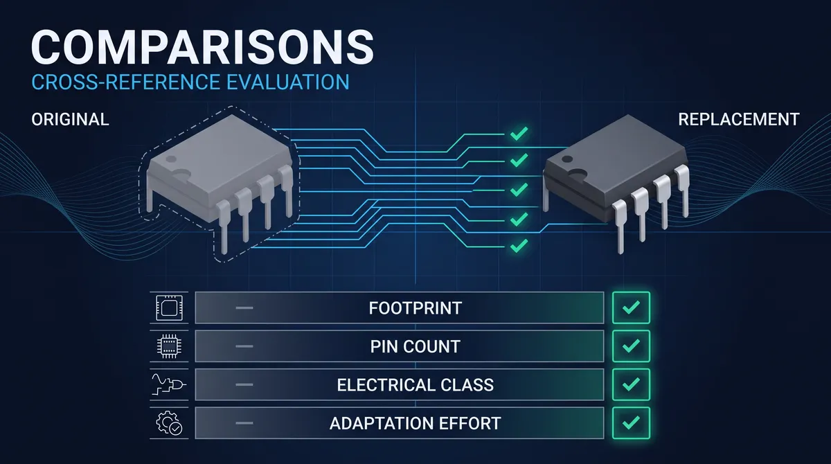
LM2596 vs LM2576 is the comparison every hobbyist and many a professional makes when they need a step-down switching regulator, because the two parts are the most common buck converters on the workbench and on the countless adjustable power modules sold online. The LM2576 is the original SIMPLE SWITCHER buck converter, a 3-amp step-down regulator that switches at 52 kilohertz, and the LM2596 is its higher-frequency successor, the same 3-amp step-down design that switches at 150 kilohertz, and the comparison between the two is a comparison of frequency more than of function. Both parts step down a wide input, up to about 40 volts and 60 in the HV grade, to a lower output, in fixed voltages or an adjustable version set by a resistor divider, and both sit in the family of pin-compatible parts that the market reproduces. This guide compares the two across the switching frequency, the inductor and the filter size, the efficiency and the heat, the input and the output options, and the applications, and it gives the rule for choosing between them, so the buck rail picks the 52-kilohertz original or the 150-kilohertz successor on the evidence.
The comparison is also the entry to the replacement view, because the LM2596 and the LM2576 belong to one of the most reproduced switching-regulator families in electronics. Both parts share a pinout that the vendors and the domestic manufacturers reproduce, and both appear on the ubiquitous adjustable buck modules, so a design that uses either has a deep, pin-compatible supply. This guide covers the engineering comparison and the sourcing view together, and it reads the two parts honestly: they are the same converter at different frequencies, the frequency difference drives the inductor and the filter choice, and the rest of the comparison follows from that one fact. The LM2596 and the LM2576 are the older and the newer face of the same SIMPLE SWITCHER family, and the comparison maps the family's frequency story.
LM2596 vs LM2576: The Core Difference
The core difference between the LM2596 and the LM2576 is the switching frequency, and every practical difference in the comparison follows from it. The LM2576 switches at 52 kilohertz, the frequency of its original SIMPLE SWITCHER design, and the LM2596 switches at 150 kilohertz, nearly three times higher, and the frequency decides the size of the inductor, the output filter, and the ripple that the converter produces. A higher switching frequency switches the inductor faster, which lets a buck converter use a smaller inductor and smaller output capacitors while maintaining the same output ripple, so the LM2596 builds a smaller, lower-profile rail than the LM2576 for the same output. The higher frequency also moves the switching noise to a higher band, which is easier to filter at the output and harder at the input EMI, so the frequency choice is a size and an EMI trade. The core difference is the frequency, and the comparison reads the frequency's consequences, the inductor, the ripple, the efficiency, and the EMI, through the rest of the guide.
The two parts also share the design that makes them siblings, because the LM2596 is the LM2576's successor rather than a different converter. Both are the original-style buck regulators with the internal switch and the internal oscillator, both deliver 3 amps, both step down from a working input of up to about 40 volts, both support the fixed outputs and the adjustable mode with the external resistor divider, and both carry the current limit and the thermal shutdown protection. The share of the design means that a designer who knows the one knows the other, and the comparison between them is the frequency trade rather than a capability contest. The LM2596 does not do what the LM2576 cannot, it does it at a higher frequency, and the comparison honors that relationship by reading the frequency as the deciding axis.
How the switching frequency changes the converter
The switching frequency changes the converter at its smallest parts, the inductor and the output capacitor. A buck converter stores energy in its inductor during the switch-on time and delivers it during the switch-off time, and a higher frequency means shorter cycles and less energy stored per cycle, so the inductor's inductance and physical size drop for the same output current and ripple. The LM2596 at 150 kilohertz typically pairs with an inductor of a few tens of microhenries and a small output capacitor, while the LM2576 at 52 kilohertz pairs with a larger inductor, often a hundred microhenries or more, and a larger bulk capacitor, for the same rail. The frequency also shapes the output ripple at the same values, because the higher frequency spreads the charge pulses and lets the filter smooth the smaller excursions. The designer who reads the frequency reads the inductor and the capacitor the circuit needs, and that single fact is the reason the LM2596 makes the smaller rail.
The Inductor and Output Filter: LM2596 vs LM2576
The inductor is the part that makes the LM2596 and the LM2576 boards look different, and the comparison of the filter is the comparison of the frequency made physical. An LM2596 buck design at 150 kilohertz uses an inductor in the tens of microhenries, often a small shielded drum, and an output capacitor that filters the 150-kilohertz ripple to the required level, and the whole rail fits in a compact footprint. An LM2576 buck design at 52 kilohertz uses a larger inductor, often a hundred microhenries or more, and a larger output capacitor, and the rail takes more board area and more height. The trade is the frequency's gift and its cost: the LM2596 saves the board space but switches the noise at the higher frequency, and the LM2576 spends the board space but switches the noise at the lower frequency. The selection reads the board's space budget and the noise budget together, because the filter that the frequency forces is the physical difference between the two rails.
The input filter and the layout follow the same frequency story, because the switched current of a buck converter is a noise source on both the input and the output. The higher-frequency LM2596 needs the input capacitor close to the part and a layout that keeps the switched loop tight, while the lower-frequency LM2576 is more forgiving of the layout and the long leads, which is part of why the older part survives in the hobby world. The ripple at the output is the same design target, set by the inductor and the capacitor values at each frequency, and a design that needs a quiet rail sizes the filter at its own frequency and adds the post-filter where the ripple budget demands. The filter comparison is the body of the frequency difference, and the designer reads the inductor, the capacitor, and the layout the frequency forces before choosing between the parts.
How to size the inductor for each part
Sizing the inductor for each part follows the datasheet's table and the frequency. The LM2576 at 52 kilohertz pairs with a larger inductance that the datasheet selects by the input voltage, the output voltage, and the current, typically a value around or above a hundred microhenries for a 3-amp rail, and a saturation-current rating above the peak switch current. The LM2596 at 150 kilohertz pairs with a smaller inductance, typically in the tens of microhenries for the same rail, and the same peak-current rating on a physically smaller part. The datasheet selects the part number, the core type, and the wire, and the designer reads the table at the operating point rather than guessing the value. The inductor size is the direct consequence of the frequency, and it is the reason the LM2596's board is smaller, which is the comparison's most visible difference.
Efficiency, Heat, and Performance: LM2596 vs LM2576
The efficiency of the LM2596 and the LM2576 is the same family story, the classic 80-percent-class buck efficiency that holds across most of the operating range, with the differences that the operating point and the switch losses bring. The LM2596's higher frequency adds a small amount of switching loss at the switch and the diode, and the LM2576's lower frequency carries the larger inductor's losses, and the net efficiency at the same output is close, with the data-sheet curves showing the practical values at each input and output. The heat follows the efficiency and the current: a 3-amp buck from a 12-volt input to a 5-volt output halves the power that the linear version would burn, and the residual wattage is shed through the package, the TO-220 tab, or the TO-263 pad and the board copper. The comparison of the efficiency and the heat is a comparison of the close values and the shared package, and the selection between the two is not decided by efficiency, it is decided by the frequency and the space that this guide's earlier sections read.
The performance also carries the response and the protection that both parts share, because the family's character is the SIMPLE SWITCHER's simplicity. Both parts need just the inductor, the diode, the capacitors, and the feedback network, with no external compensation, because the internal comp is designed for the fixed frequency, and both carry the current limit and the thermal shutdown that protect the part and the load. The startup, the soft-start, and the response to the load step differ in the detail, and the datasheet's curves show the behavior, but neither part is the fast-responding, feature-rich converter of the newer families. The performance comparison is the family's shared boundary, and the preference for the two parts is a preference of frequency and space rather than of capability. The efficiency and the heat are the family's honest numbers, and the frequency is the family's differentiator.
How the switching loss changes with the frequency
Switching loss is the energy lost every time the switch turns on and off, and it scales with the frequency because the higher frequency multiplies the number of transitions. The LM2596's 150 kilohertz transitions three times as often as the LM2576's 52 kilohertz, so the switch and the diode at the higher frequency carry a larger share of the switching loss, all else equal, and the efficiency curves at the light load can show the difference. The practical magnitude depends on the switch's rise and fall time, the diode's recovery, and the inductor's AC resistance, and at the normal 3-amp operating points the two parts land close, with the lower-frequency part often a touch more efficient at the heavy load and the higher-frequency part holding the edge in the small-filter solutions. The designer reads the efficiency curves at the specific input and output, rather than comparing the two parts by a single number, and the honest conclusion is that the frequency decides the size and the EMI, and the efficiency follows the curves rather than the part number.
Input Range, Output Options, and Protection: LM2596 vs LM2576
The input range and the output options of the two parts are the same, because the family shared the specification, and the comparison reads them as shared rather than as differences. Both step down from a working input of up to about 40 volts on the standard grade and about 60 volts on the HV grade, both deliver the output in the fixed versions, 3.3, 5, 12, and 15 volts in the classic lineup, or in the adjustable version whose output is set by the external resistor divider, and both regulate the output with the family's accuracy and the load and the line behaviors the datasheet states. The shared input and output specification means a design that runs the LM2576 can run the LM2596 on the same input and output, because the numbers match, and the frequency is the only difference the board sees. The protection, the current limit and the thermal shutdown, is also shared, and the input filter and the reverse and the surge protection the datasheet recommends apply to both. The shared ground is the reason the comparison is a frequency decision rather than a capability decision.
The HV grade deserves its own read, because it is the variant that widens the family's reach. The LM2576HV and the LM2596HV accept an input up to about 60 volts, which serves the 48-volt industrial and the telecom buses, and the HV parts carry the same frequency difference as the standard parts, the 52-kilohertz LM2576HV and the 150-kilohertz LM2596HV. The designer who works the higher input reads the HV grade and the same inductor-and-filter frequency trade, and the comparison's rule carries across the grade. The input and the output options are the family's shared breadth, and the HV grade extends the breadth, and the comparison of the two parts holds at every grade because the frequency difference is the constant. The shared ground and the shared breadth keep the comparison clean, and the frequency remains the axis of the choice.
Fixed versus adjustable output in the buck family
The fixed-versus-adjustable output in the buck family follows the same rule that the rest of the regulator families use. Choose the fixed part, the LM2576-5.0 or the LM2596-5.0, when the rail is a standard voltage and the design wants the precise output with no external divider, and choose the adjustable part when the rail is a non-standard value or the same board must serve several outputs by changing a resistor. Both fixed and adjustable versions carry the same frequency difference between the LM2596 and the LM2576, so the fixed-versus-adjustable choice is independent of the frequency choice, and the designer selects the output architecture and the frequency separately. The adjustable buck is the version behind the ubiquitous modules, and the fixed buck is the production rail, and the comparison covers both under the same frequency rule.
When to Choose the LM2596
Choose the LM2596 when the board's space and height matter, because the 150-kilohertz frequency lets the rail use the smaller inductor and the smaller output filter, and the lower-profile solution is the LM2596's reason to exist. Choose it when the design prefers the modern, more compact rail, when the board is dense and every cube-millimeter counts, and when the slightly higher-frequency EMI can be contained by the layout and the input filtering that the higher frequency demands. Choose the LM2596 for the newer builds, the module designs, and the boards where the smaller inductor is the deciding advantage, because the frequency's gift is the space it saves. The LM2596 is the answer to the compact rail, and the comparison's rule is to let the newer part own the space-constrained buck.
The 2596 choice also reads the ecosystem, because the LM2596 and its modules are the workbench standard, and the parts and the community around the adjustable modules are vast. A prototype that uses the LM2596 module translates easily to the production LM2596 on the board, and the fixed and the adjustable versions and the HV grade cover the range, so a design that standardizes on the LM2596 has a deep and practical supply. The replacement view holds because the pinout is standardized across the vendors and the domestic parts, and the sourcing is deep because the part is a workbench classic. The LM2596's story is the compact converter and the module ecosystem, and the guide's view matches, the right frequency, the small filter, and the deep family.
When to Choose the LM2576
Choose the LM2576 when the board has the space and the design values the lower switching frequency, because the 52-kilohertz rail switches its noise in the lower band and is more forgiving of the layout and the long leads, which suits the less-dense boards and the retrofit designs. Choose it when the design runs the loads where the lower-frequency converter's switching loss is a touch lower, and when the larger inductor is acceptable in exchange for the lower-frequency EMI that the older part's design inherits. Choose the LM2576 for the boards that already use it, the mature designs, and the applications where the frequency's noise at the higher band would complicate the filtering, because the older part's trade is the space it spends. The LM2576 is the answer to the space-forgiving rail and the lower-frequency EMI, and the comparison's rule is to let the original part own the quiet-layout buck.
The 2576 choice also reads the family's heritage, because the LM2576 is the SIMPLE SWITCHER original that the industry has produced and serviced for decades. The datasheet is mature, the APPnotes are extensive, the community knows the part, and the part and its modules are in stock everywhere, so a design that chooses the LM2576 inherits a deep, well-documented supply. The replacement view holds at the same pinout and the same package, and the sourcing spans the vendors and the domestic parts. The LM2576 is the older face of the family, and its story is the proven rail and the deep documentation, and the guide treats it as a real choice rather than as the outdated also-ran, because the space-and-noise trade is a legitimate engineering decision.
How to Design a Buck Converter Around These Parts
Designing a buck converter around the LM2596 or the LM2576 is a small component-selection exercise, and the worked example makes the difference between the two parts concrete. Take the common rail: a 12-volt input, a 5-volt output, and a 1-amp load. The first selection is the diode, which must be a fast-recovery or a Schottky type rated for the input voltage plus a margin and for the average forward current, because the diode conducts during the switch-off time when the inductor freewheels, and a slow diode burns more of the efficiency and runs hotter. The second selection is the inductor, and here the two parts part ways: the datasheet's inductor-selection table gives the value by the input voltage, the output voltage, and the current, and for the 12-volt-to-5-volt, 1-amp rail the LM2596 at 150 kilohertz typically selects an inductor in the 33-microhenry class with a saturation-current rating above the peak switch current, while the LM2576 at 52 kilohertz selects a value in the 100-microhenry class for the same rail. The third selection is the output capacitor, which the datasheet sizes by the output ripple and the stability, a low-ESR part in the 220-microfarad class for the LM2596 and a larger bulk in the 330-microfarad class for the LM2576, with the low ESR and the ripple current rating read against the load. The fourth selection is the input capacitor, a 100-microfarad-class electrolytic placed close to the part to handle the switched input current. The feedback is last: the fixed versions need no divider, and the adjustable versions set the output with two resistors using the family's reference, and the divider's tolerance joins the output tolerance.
The worked example also reads the layout, because the buck converter's switched current is a noise source that the layout tames or releases. Keep the switched loop tight, the input capacitor, the switch, the diode, and the inductor, in the smallest loop, because the loop's area is the antenna for the noise that the input and the output filtering then cannot fully catch. Place the part, the diode, and the inductor close together, and the feedback trace away from the switched node, so the reference does not pick up the switching noise. The layout discipline is the difference between the converter that works on the bench and the one that passes the EMI test, and it is the same discipline at either frequency. The 150-kilohertz LM2596 needs the tighter layout and the closer input capacitor, and the 52-kilohertz LM2576 is more forgiving, which is the frequency's physical consequence repeated at the board level. A design that follows the datasheet's layout guidance builds the rail that the module vendors have already proven, which is the practical completion of the component selection.
A worked inductor and capacitor selection table
A worked selection table makes the design concrete, and it is the table the module builders effectively use. For the 12-volt input and the 5-volt, 1-amp output: the LM2596 selects an inductor near 33 microhenries, a low-ESR output capacitor near 220 microfarads, a Schottky diode rated near 40 volts and for the 1-amp average, and an input capacitor near 100 microfarads; the LM2576 selects an inductor near 100 microhenries, an output capacitor near 330 microfarads, the same diode class, and the same input capacitor. The values come from the datasheet's selection tables, and the designer reads them at the operating point rather than from memory, because the table accounts for the input voltage, the ripple, and the stability that a single number cannot. The inductor's saturation current is the check that the table glosses: the peak switch current, the average plus half the ripple, must lie below the inductor's saturation rating, or the inductor saturates, the inductance collapses, and the converter loses the efficiency and the regulation. The capacitor's ripple current is the second check, because the switched current through a small case overheats it, and the low-ESR and the ripple-current rating are read together. The table turns the datasheet into the design, and the design turns the LM2596 or the LM2576 into a working rail.
Efficiency and Thermal: A Worked Calculation for the LM2596 and the LM2576
The efficiency and the thermal behavior of the buck family are best seen in a worked calculation, and the numbers are the honest face of the comparison. Take the 12-volt-to-5-volt, 1-amp rail: the output power is 5 watts, and at the family's typical efficiency of about 80 percent, the input power is the output power divided by the efficiency, about 6.25 watts, so the converter dissipates the difference, about 1.25 watts, across the switch, the diode, and the inductor. Compare that against the linear regulator on the same rail, which dissipates the input-minus-output difference times the current, about 7 watts, and the buck's 1.25 watts is the reason the switching regulator exists, the heat is a fraction of the linear's, and the board does not need the huge heatsink. The junction temperature of the buck's switch follows the dissipated power and the package: a TO-220 with the fair-air thermal resistance in the 50-degree-per-watt class runs the junction at about 25 degrees ambient plus 1.25 times 50, about 87 degrees, inside its 125-degree rating but warm, and a heatsink or the board copper brings it down to a cool 40 degrees. The calculation is the same for both parts, and the difference between the two is the switching-loss detail rather than the headline.
The switching frequency adds its own small term to the thermal, and the worked number shows why it rarely decides the choice. The LM2596 at 150 kilohertz transitions three times as often as the LM2576 at 52 kilohertz, and each transition burns a small switching loss in the switch and the diode, so the higher-frequency part carries a touch more switching loss on the same rail, and the efficiency curves at the light load can show the difference. The magnitude at the normal operating points is a few points at most, and the datasheet's efficiency curves state the actual values at each input and output, so the designer reads the curve at the operating point rather than comparing the parts by a single figure. The thermal worked calculation therefore ends where the selection began: the frequency decides the inductor and the filter and the layout, and the efficiency and the heat follow the curves and the package, and a rail that fits on the board at the package's thermal ability is served by either part with the numbers the datasheet shows. The worked calculation is the number behind the "80-percent class" that the catalog copy quotes, and it is the number the thermal design uses.
Measuring Output Ripple and Noise on the Bench
Measuring the output ripple and the switching noise of the LM2596 or the LM2576 is a bench procedure that confirms the filter design, and the correct measurement setup is half the result. Use an oscilloscope with a 10x probe and a short ground lead, or the probe's ground spring, and measure directly across the output capacitor, because the long ground lead picks up the loop noise that the measurement mistakes for the spec. Set the scope AC-coupled and apply the 20-megahertz bandwidth limit, which rejects the broadband noise and reveals the switching ripple that the datasheet specifies. The read shows the ripple at the switching frequency, the 150-kilohertz ripple for the LM2596 and the 52-kilohertz for the LM2576, with the amplitude in the tens of millivolts for a well-sized filter, and the spikes at the switching edges are the fast noise that the bandwidth limit removes. The measurement is the confirmation that the inductor and the capacitor table was sized correctly, and it is the number that the design records beside the load test.
The measurement also reads the load step, which is the transient the filter must hold. Apply a load step from 20 to 80 percent of the rating with the electronic load, and observe the output on the scope, the droop at the step and the recovery and the ringing, and compare the result against the datasheet's transient response. A larger output capacitor and a lower ESR tighten the response, and a layout with the long loop relaxes it, so the load-step read is the interface between the filter and the layout. The same measurement runs on the fixed and the adjustable versions, and the feedback divider's layout shows in the noise that the adjust pin picks up, which the bypass capacitor on the adjust pin cures. The ripple and the load-step measurements are the bench half of the filter design, and a converter that reads clean on the scope is a converter whose datasheet values the board has confirmed, which is the completion of the design process that the selection table started.
Troubleshooting Buck Converter Problems
The buck converter problems that appear on a new board are consistent, and the troubleshooting runs on a short list of checks. If the output does not regulate, check the input voltage against the part's minimum and the dropout, check the feedback divider wiring in the adjustable version, and check for a missing or a wrongly placed enable pin, because a fixed part with no enable simply needs the input, while the adjustable part needs the divider to land. If the output oscillates or the board buzzes, the usual suspects are the inductor reaching saturation, the output capacitor's ESR outside the datasheet window, or a layout loop that the switched current is exciting, and the fix is the larger inductor with the higher saturation rating, the correct capacitor, and the tight loop. If the part overheats, check the diode, a slow rectifier adds the recovery loss, check the inductor's AC resistance, and check the board copper under the part, because the thermal path is part of the rating. If the output whines at the ceramic-capacitor frequencies, the fix is the layout and the capacitor values that the datasheet recommends, and the whine is the piezoelectric ceramic or the inductor core singing at the switching frequency. The troubleshooting list is the practical bookend to the design, and it is the checklist a designer keeps for the first board of every buck rail.
The Adjustable Module Version and Its Design
The adjustable module is where most engineers first meet the LM2596 and the LM2576, and understanding the module's design explains the part's practical world. The ubiquitous buck module is built around the adjustable version, with a trimmer or a fixed-resistor divider setting the output, a potentiometer on the board for the knob, an input capacitor, an output capacitor, the inductor, the diode, and often a status LED, and the whole assembly is the datasheet's adjustable application made physical. The module's trimmer sets the output through the reference divider, and the same circuit with the trimmer replaced by the fixed resistors is the production rail, which is why a module design translates directly to a board design. The module also shows the parts each design needs, the inductor the frequency selected, the diode, and the capacitors, and a designer who reads a module can read the board. The module is the part's introduction, and the datasheet is its completion, which is the path the worked example in this guide follows.
The module version also carries the design choices that every build inherits. The trimmer adds the tolerance to the output, so the module's nominal voltage is only as accurate as the trimmer and the reference, and a production design replaces the trimmer with the precision fixed resistors. The module's layout is the compact loop that the datasheet recommends, which is why the module performs as well as it does for its size, and a board that copies the module's layout inherits its behavior. The status LED and the trimmer draw their small currents from the rail, and the module's reported accuracy ignores them. The module design is the practical template, and the worked table and the layout notes in this guide are the analysis behind the template, so a designer who starts with a module and moves to a production board reads the same circuit in both places. The module is the workbench face of the LM2596 and the LM2576, and the design this guide describes is the same face drawn on the board.
LM2596 vs LM2576: Equivalents and Replacements
The replacement view of the LM2596 vs LM2576 comparison is the sourcing that both choices open, and it is the same view for both parts. Both sit in the buck family whose pinout the vendors and the domestic manufacturers reproduce, and the fixed and the adjustable and the HV grades cover the range, so a design that chooses either has a deep, pin-compatible supply. The replacement qualification runs the same discipline as any substitution: confirm the package and the pinout, the TO-220 or the TO-263, confirm the frequency is the part's own, because the LM2596 and the LM2576 are not interchangeable at the same pinout without changing the inductor and the filter, confirm the input and the output, and test the replacement on the board across the load and the temperature. The replacement is pin-compatible within the family, and the frequency difference means a designer who swaps the 2576 for a 2596, or the reverse, rechecks the inductor and the filter rather than assuming the old values hold.
The comparison also names the siblings that surround the two parts, because the LM2596 and the LM2576 belong to a family with more members. The LM2676 and the LM2673 and the related SIMPLE SWITCHER parts, the newer synchronous converters, and the domestic pin-compatible buck regulators all serve the same step-down role at the same and different frequencies, and the selection between the 2596 and the 2576 is one pair within a wider family. A designer who reads the LM2596 vs LM2576 comparison this way chooses by the frequency, the space, and the EMI budget, secures the chosen part through the family's deep supply, and rechecks the filter whenever the frequency changes, and that discipline is the working answer that the schematic and the board both accept.
Not sure which sensor fits your project?
Talk to our mmWave application engineers for a free consultation.
Specify your hotel project with our engineers
Send your room count, ceiling type, and protocol preference. We will return a sample plan and quote within 24 business hours.
- Move from general guidance into a product or application discussion.
- Use RFQ when pricing, drawings, MOQ, or launch timing needs structure.
- Keep a direct contact path visible for fast clarifications and handoff.